Archive for the ‘Conversion’ Category.

Transfer Pump Failure

Short recap for those unfamiliar with my setup:  My truck stores WVO in a pair of 60gal GFS Trekker tanks.  I treat the rear-most tank as my “dirty” tank and only pump WVO into that tank.  I treat the forward-most tank as my “clean” tank and feed the 7.3L PSD engine from that tank.  Each time WVO leaves a tank, it passes through a Racor 1000 fuel filter and a 2020SM (2-micron) filter.

I use a small 12V gear pump to transfer WVO from the “dirty” tank to the “clean” tank.  The WVO is pulled out of the “dirty” tank, through the Racor 1000, through this 12V gear pump, and then sent to the “clean” tank.  I use a switch in my dash to turn the pump on/off.  Do NOT forget to monitor the fuel level in the “clean” tank.  I have had a big mess on more than one occasion because I pumped too much WVO into the “clean” tank.

This transfer pump failed (again).  The first failure occurred in 11/2009.  I do not recall why it failed and did not seem to write about it.  This time, I left the pump running for a very long time and ruined it.  Golden Fuel Systems sold a replacement “One/Half Shot Pump – OSP01” for around $260 after S&H in 2009.  I received a Fill-Rite FR1602 pump.  I learned that GFS would remove the gear pump from the enclosure and discard the enclosure.  The internal pump that Fill-Rite was using in the FR1602 is a “Marco UP3/OIL 12V gear pump” (P/N: M164-020-12).

I contacted GFS to purchase another replacement.  They informed me that they are unable to provide an exact replacement (Fill-Rite discontinued the FR1602).  They are now selling a much more expensive GFS Gathering Pump Kit for $415+S&H.  The new pump may be superior (or not), but I preferred an exact replacement because I had already fabricated a custom mount that allowed me to attach the “Marco UP3/OIL 12V gear pump” to the side of my fuel tanks between the two Racor 1000 filters.  I was able to find several FR1602 and Marco UP3/OIL products in the $225-250 range.  Sharing in case anyone else is needing to replace this pump, but did not have the Fill-Rite or Marco part numbers.  Good luck!


gfs-marco-up3-oil-12v-gear-pump

WVO kit installation (session 3) …

This is the third weekend of work on the WVO conversion.  To recap, we pre-drilled holes before installation of spray-on bed liner the first weekend, we mounted tanks and plumbed coolant to heat exchangers the second weekend.

This weekend we finished plumbing and wiring in the bed, into the fuel system, and under the hood.  We put about 10-gal of diesel #2 in each 60-gal tank.  We built the bracket below so that we could mount the onboard 3-gpm pump to the side of the tanks (between Racor filters).  We ran a spare wire to the bed to power the collection pump.  We plumbed the Pollak 6-port valve into the fuel system.  We installed the six-fuse block and relays under the hood.  We ran electrical into the cab.  We began work on wiring harnesses for the 3 gauge pod (front fuel level, rear fuel level, fuel vacuum).  This was a LONG day because we thought we’d be able to finish.  We called it a night at 3-4AM and figured we’d finish the electrical later.  For now, the factory/diesel side of the Pollak valve is open.

Picture of the custom mounting bracket for the onboard 3-gpm pump:

20090121-wvo-pump-bracket

The truck started right up when we were finished.  I only made it about two blocks before the truck died.  We forgot to prime the fuel lines.  I had a vacuum for this, but we simply forgot to use it.  I immediately suspected that air had worked it’s way up to the IP and it wasn’t getting any fuel.  We weren’t able to start it, so we ended up towing it back to the shop and putting it on the charger.  We tried starting it a few times again the next morning to no avail.  I’d crank for 5-7 seconds, then wait about 60 seconds.  Repeated at least 20-30 times.  Put it back on the charger and took a break for lunch.

I sent out an SMS to several farm and truck friends asking for advice.  Several people suggested opening the injector relief valve.  I was unable to locate anything like this.  Instead, I opened the water drain valve on the back of the fuel filter (aka fuel/water separator).  I turned the ignition to start (but not all the way to crank) so that the fuel pump could pressurize the system again.  I opened the valve again.  I could tell that liquid was draining the second time.  After that, the truck started right up but still occassionally stuttered (small air bubbles in system?) so I forced it to idle high (1500-2000) for about 12-15 minutes.  RPM would occasionally drop, but never enough to die since it was idling high.  It was acting pretty normal after about 8-10 minutes, so we called it good.  I had no other issues running off the factory diesel tank after that.

UPDATE:  02/23/2009

I located the hot wires I needed under the dash.  I finished prep work for the gauge wiring harness, labeled gauge and switch wiring.  I left the radio play the whole time .. and the headlights on.  Oops!  I couldn’t start the truck to move it out of the garage because battery was too low.  I jumped the truck, moved it, put it on charger for the night.

UPDATE:  02/24/2009

The truck seemed fully charged and started right up in the morning.  It didn’t start when I tried to leave the office for a lunch meeting, so I got a jump from someone at the business next door.  The truck didn’t start after my lunch meeting either.  We tried to jump it, but weren’t getting a spark at all.  Mike towed me to the repair shop, where they quickly determined that my starter had failed.  Well crap.  Wish I’d known about the relief valve before I worked my starter to death trying to purge air from the fuel system two days ago.  They also confirmed that my batteries had a full charge, which explained the no spark.  You’ll only see a significant spark between batteries if there is a significant difference in chages between the batteries.  It is unlikely that the jump start before lunch actually helped the truck start.

WVO kit installation (session 2) …

The spray-on bed liner was installed this week, so we were ready to begin some real work on the conversion this weekend.

We mounted the pair of 60-gal Trekker tanks.  We ran the Parker 3B hose from the tanks up to the engine compartment.  We separated the fuel line from the rest of the lines near the fuel pump.  (UPDATE:  We should have separated the fuel line a little further back, because we ended up mounting the 6-port Pollak valve on the frame between the fuel tank and the transmission support/mount.  We thought we were going to be able to mount the valve right by the fuel pump, but just couldn’t figure out how to make it fit.   I ended up separating the fuel hose from the other hoses by hand, but that was a lot more time consuming since the 3B hose was already in position.)  We separated the electrical lines from the coolant lines when the hose entered the engine compartment.  We ran the pair of coolant lines above the engine to the passenger side of the engine compartment and kept them wrapped in the sheath.

We cut the coolant lines going to/from the heater core and installed each “T” and connected each coolant line.  We determined which line was the “source” and which was the “return” by running both lines into a bucket in the bed and waiting for coolant to come out of one of the lines.  We connected the “source” to the front/clean tank and connected the “return” to the rear/dirty tank.  We had to add about 1/2-gal of coolant right away.  In the end, I probably added a total of 1 gallon of 50/50 universal coolant.

UPDATE:

If I were to do this again, I’d want to be 100% sure that I knew where we were mounting the 6-port valve.  Everything else went pretty smoothly.  Having pictures that show where to run the 3B hose would have probably cut down on planning/thinking, though we managed fine on our own with a little extra time.  It would have also been nice to know that it can take a good 10 minutes for the truck to fill the entire length of the “source” coolant hose going back to the bed/tanks.  We were worried that something was wrong when we weren’t seeing any coolant back there after 4-5 minutes.

WVO kit installation (session 1) …

Preparing truck bed for WVO tank installation …

I’ve decided to replace the drop-in bed liner with a spray-on bed liner before we mount the GFS tanks in the bed.  This weekend we took inventory of all the items received from Bud and GFS.

I’ve been told that there are no really good local Rhino Liner installers, so opted to go with the local Line-X folks.  They took a look at the truck while the drop-in liner was present and gave me a quote.  Since they couldn’t take a look at the entire bed because of the drop-in bed liner, they warned that large amounts of rust could drive up the price and said that sanding down the rust and treating the areas with self-etching primer could cut down on costs.  We planned to work on the rust this weekend, but were pleasantly surprised that rusting was fairly minimal so we just drilled necessary holes for tank mounting, filter draining, and the fuel/coolant/electrical lines.

Truck bed with the drop-in bed liner.

20090118-truck-bed-liner

Truck bed without liner.  Tanks are in position.  Marking holes to be drilled.

20090118-truck-bed-no-liner

My body shop friend took my drop-in bed liner.  Sounds like he will be able to use the liner in his truck.  If not, told him they were welcome to use it for anything.  I was just glad to see it go to use.  If he didn’t need it, I would have listed it on CL.  No reason to store it.  Better than cutting it up and throwing it in the garbage!

Top view of dual 60 gal Trekker tanks.  GFS recommends mounting these with the filters on the driver’s side, but what do they know.  It’s not like they’ve been doing this for 8 years or anything.  I want to be able to do all of my filling on the driver’s side.  You can see a fuel fill port near the far left edge of each tank, a larger access port (for cleaning, etc?) near the center of each tank, and a custom-built mount for the heat exchangers, fuel pickups, and fuel fill ports (2 per tank), and fuel sending units on each tank.  The Racor 1000 filters are mounted on the passenger side.

UPDATE:  I later decided that I’m glad all the fill ports are on the driver’s side, but wish we had drilled the mount holes for the tanks maybe one more ridge to the left.  The extra few inches would have allowed for easier access to the drain bowls on the bottom of the Racor 1000 heated filters.  I can blindly drain samples into containers to check for water now, but It’d be nice to be able to visually check the front filter, though that one is the least likely to accumulate water since everything runs through the rear/dirty tank and filter first.

20090118-gfs-kit-1

The GFS triple-bypass (3B) hose, manufactured by Parker.  UPDATE:  The Ford kit barely included enough hose.  Would have had extra if we mounted the tanks with the filters on the driver’s side, as per GFS recommendation.

20090118-gfs-kit-2

Cross-section view of the GFS triple-bypass (3B) hose.  Two 1/2″ Parker coolant hoses, one 3/8″ Parker fuel hose, 4 electrical lines for front tank fuel gauge, rear tank fuel gauge, onboard 3gpm transfer pump (from rear tank, through rear filter, to front tank), and a 10# for the pair of 300W filter heaters.  I had to use the truck frame as common ground and had to run an extra line for power to the 7gpm collection pump.

20090118-gfs-kit-3

All of the GFS items (including large tanks) were well packed.  Everything I received came in 5 boxes:  front tank, rear tank, 7gpm pump (not shown), filters and gauge pod, everything else.

20090118-gfs-kit-4

Better shot of the box with filters and gauge pod.  I expected to receive an a-frame pod, but am glad I received the under dash pod since that will leave room for me to grow into some other gauges (pyro, boost, oil pressure, etc) on my a-frame down the road.

20090118-gfs-kit-5

Shot of some of the boxes received in the larger misc box.  The only documentation that I originally received was an invoice with an inventory of kit items/boxes, so I could tell that I had received everything marked on the inventory sheets but had no idea how most of it was to be installed.  I was pretty intimidated by this at first, but started to sort things out.  Things made a LOT more sense after Bud provided a copy of the GFS Ford Kit installation instructions.  Glad I asked him about instructions!

20090118-gfs-kit-6

Another shot of misc hardware that came with the kit.

20090118-gfs-kit-7

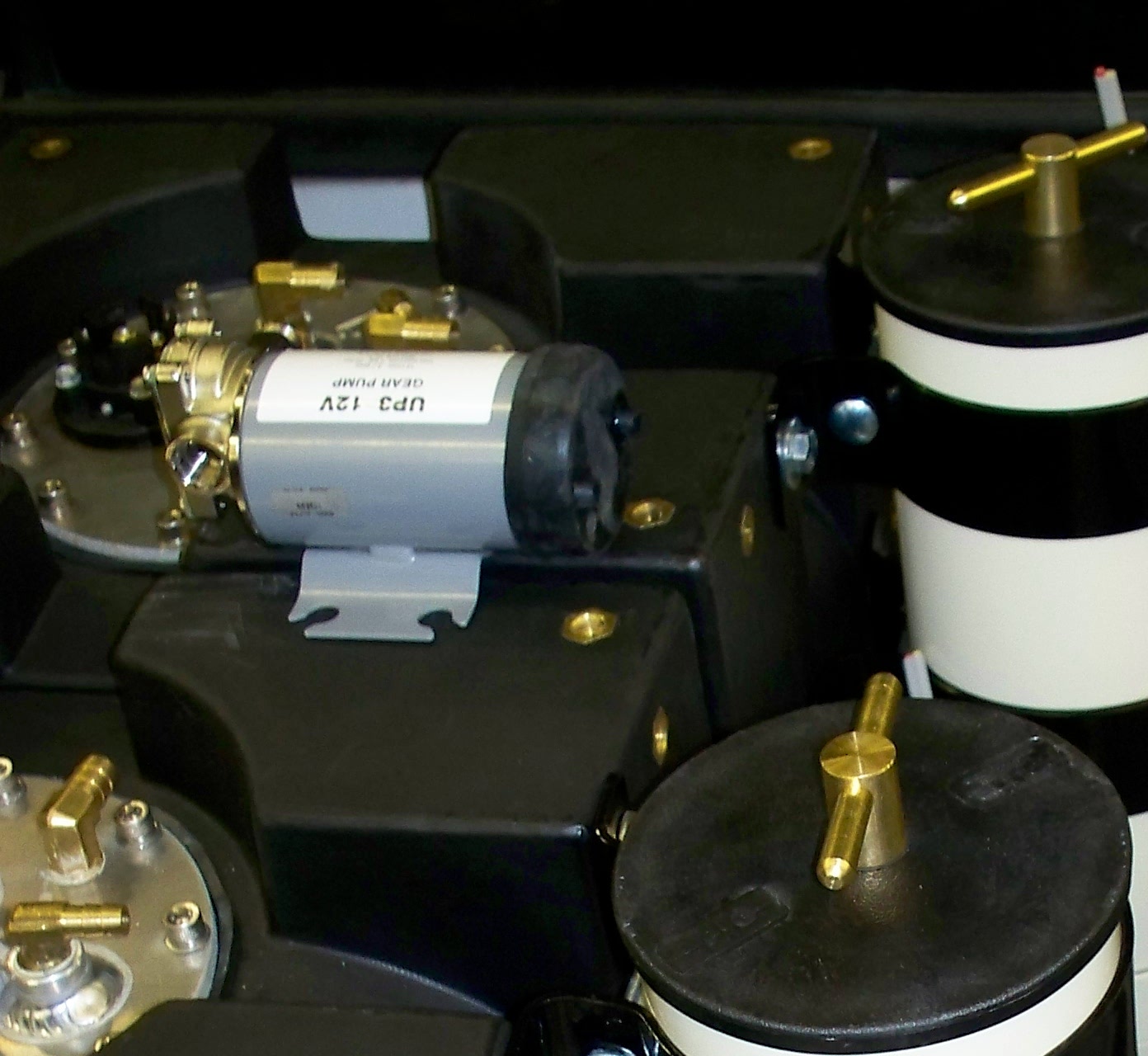
UPDATE:  In the end, we had to buy a little extra fuel hose and a few different fittings since we mounted the tanks opposite what GFS expects.  I guess they wanted us to use the 1/2″ coolant hose with the 1/2″ fuel connectors, but I sprung for a few feet of 1/2″ fuel hose.  It seems GFS usually mounts the 3gpm pump to the out port on the Racor 1000.  That wasn’t going to work with our configuration, and seemed like a bad idea anyway.  We made a bracket so that we could mount the pump on the tanks between the filters.  We also ended up NOT using most of their electrical connectors.  In some cases we used solder and heat shrink tubing, in other cases we used our own (better) connectors and applied a drop of solder after crimping each connection.  We also mounted a 6-fuse block under the hood rather than using their in-line fuse holders.  More on this later, when I have time to describe some of the other customizations I came up with to make things more user friendly.